Laser pipe cutting machines are at the forefront of modern metal fabrication, offering unparalleled precision, speed, and versatility for cutting various types of pipes, tubes, and profiles. Unlike traditional cutting methods, laser technology allows for intricate designs, clean edges, and minimal material distortion, making it ideal for industries ranging from automotive to construction.
Here’s a step-by-step guide to the process of laser pipe cutting:
Step 1: Design and Programming – The Digital Blueprint
The process begins long before any physical cutting takes place, with meticulous design and programming.
- CAD (Computer-Aided Design): The desired pipe or tube design, including all cuts, holes, and contours, is created using CAD software. This digital model ensures accuracy and allows for complex geometries.
- CAM (Computer-Aided Manufacturing) Software: The CAD design is then imported into CAM software. This software generates the specific cutting path, laser parameters (power, speed, focus), and machine movements required to execute the design. It optimizes the cutting sequence to minimize waste and maximize efficiency.
- Nesting: For multiple parts from a single pipe length, nesting software is often used to arrange the parts efficiently, reducing material scrap.
- Machine Code Generation: The CAM software translates the optimized cutting plan into G-code or other machine-specific commands that the laser cutting machine can understand and execute.
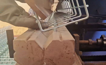
Step 2: Material Loading – Preparing the Raw Stock
The raw pipe or tube material is prepared for the cutting process.
- Material Selection: The correct type and size of pipe (e.g., steel, stainless steel, aluminum, copper) are selected based on the application.
- Loading System: Pipes are typically loaded onto the machine using automated or semi-automated loading systems. These can include bundle loaders for high-volume production or manual loading for single pieces.
- Clamping and Alignment: The pipe is securely clamped at both ends by chucks or collets that rotate and move along the machine’s axis. Precise alignment is critical to ensure accurate cuts along the entire length of the pipe.
Step 3: Laser Setup and Calibration – Fine-Tuning the Beam
The laser system itself needs to be properly configured for the specific material and cut.
- Laser Source Activation: The laser source (e.g., Fiber laser, CO2 laser) is activated. Fiber lasers are increasingly common for pipe cutting due to their efficiency and ability to cut reflective materials.
- Nozzle Selection: The appropriate nozzle size and type are chosen based on the material thickness and desired cut quality.
- Assist Gas Selection: An assist gas (e.g., oxygen, nitrogen, compressed air) is selected and supplied. Oxygen is used for exothermic cutting (mild steel), while nitrogen is used for clean, dross-free cuts (stainless steel, aluminum).
- Focusing Lens Adjustment: The laser beam is precisely focused at the material’s surface or slightly below it, depending on the material and thickness, to achieve the optimal kerf (cut width) and cut quality. This is often done automatically by the machine.
- Calibration: The machine’s sensors and optical components are calibrated to ensure the laser beam is perfectly aligned and the cutting parameters are accurate.
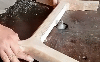
Step 4: The Cutting Process – Precision in Motion
This is the core of the operation where the laser beam interacts with the material.
- Beam Delivery: The high-power laser beam is delivered from the laser source, through a series of mirrors or fiber optic cables, to the cutting head.
- Cutting Head Movement: The cutting head, which contains the focusing lens and nozzle, moves precisely along the programmed path around and along the pipe. Modern machines often have 3D cutting capabilities, allowing for bevel cuts and complex contours.
- Pipe Rotation and Translation: As the cutting head moves, the pipe itself rotates and/or translates (moves linearly) along its axis, allowing the laser to cut around the circumference and along the length. This synchronized movement is controlled by the CNC system.
- Material Vaporization/Melting: The concentrated laser beam heats the material rapidly, causing it to melt or vaporize. The assist gas then blows away the molten material or slag, creating a clean cut.
- Real-time Monitoring: Sensors often monitor the cutting process in real-time, detecting issues like loss of cut or nozzle contamination and making adjustments or alerting the operator.
Step 5: Part Ejection and Collection – Handling the Finished Pieces
Once the cuts are complete, the finished parts are separated from the raw material.
- Part Separation: The cut parts are either automatically separated from the remaining pipe skeleton or are designed to be easily broken off.
- Unloading System: Finished parts are collected in a bin or conveyed to a sorting area. The remaining pipe skeleton is ejected as scrap. Automated unloading systems are common for high-volume production.
Step 6: Post-Processing and Quality Control – The Final Check
The cut parts undergo final checks and any necessary finishing.
- Deburring (Optional): While laser cutting produces very clean edges, some materials or specific cuts might require minor deburring to remove any tiny burrs or sharp edges.
- Cleaning: Parts may be cleaned to remove any residue from the cutting process.
- Quality Inspection: Each cut part is inspected for dimensional accuracy, cut quality (smoothness, dross-free edges), and adherence to design specifications. This ensures the parts are ready for the next stage of manufacturing or assembly.
Laser pipe cutting machines revolutionize the fabrication of tubular components, offering unmatched precision and efficiency. Their ability to create complex cuts and designs with minimal waste makes them an indispensable tool in various industries.