The cutting disc, or wheel, is the operational heart of many powerful tools, including angle grinders, cut-off saws, and abrasive chop saws. Whether you’re slicing through metal, concrete, tile, or stone, the disc is subjected to immense friction and stress. Over time, these discs wear down, lose their effectiveness, or become damaged, necessitating a replacement.1 The process of changing a cutting disc is routine for many tradespeople, but it is one that demands strict adherence to safety protocols and technical precision to prevent serious injury and ensure optimal tool performance.
⚠️ Safety First: Essential Preparations
Before attempting to change any part of a power tool, safety is paramount. Ignoring these steps is the most common cause of accidents during tool maintenance.
1. Disconnect Power
The most critical step is to eliminate any possibility of the tool accidentally starting.
-
Corded Tools: Unplug the power cord from the wall socket. Do not simply turn off the tool’s switch.
-
Cordless Tools: Remove the battery pack completely from the tool body.
2. Personal Protective Equipment (PPE)
Although the tool is off, the worn disc and tool components can still pose hazards.
-
Safety Glasses: Must be worn to protect against flying debris or fragments from a damaged disc.2
-
Work Gloves: Recommended to protect hands from the sharp edges of a damaged or worn disc, as well as the grinder’s components.
3. Allow for Cooling
If the tool was recently used, the cutting disc and the associated spindle components (flanges/nuts) can be extremely hot. Allow several minutes for the tool to cool down before handling.
🛠️ Understanding Disc and Tool Compatibility
Selecting the correct replacement disc is just as important as the replacement process itself. An incompatible disc can disintegrate at high speeds, leading to catastrophic failure.3
1. Check Specifications
Verify that the new disc matches the tool’s requirements, which are typically listed on the tool’s body or in the user manual. Three key specifications must match:
| Specification | Requirement |
| Diameter | The physical size of the disc (e.g., $4.5”$ or $7”$) must match the tool’s guard size. |
| Arbor Size | The size of the hole in the center of the disc (e.g., $5/8”$ or $7/8”$) must fit the tool’s spindle. |
| Maximum RPM | The disc’s rated maximum revolutions per minute (RPM) must be equal to or greater than the tool’s maximum RPM. |
2. Material Match
Ensure the disc is designed for the material you intend to cut. Using a disc designed for steel on masonry, or vice versa, will result in poor performance and rapid wear. Common disc types include:
-
Type 1 (Flat): General cutting applications.
-
Depressed Center Type 27 (Hubbed): Used for grinding, but also some cutting where the hub is necessary for clearance.
-
Diamond Wheels: Used for cutting hard, non-metallic materials like concrete, tile, and stone.
🔄 Step-by-Step: Removing the Old Disc
The exact mechanism may vary slightly between manufacturers, but the core principles remain the same. This guide focuses on the most common tool: the angle grinder.
1. Position the Tool
Place the tool on a stable, flat surface with the disc facing up. This allows for clear access and prevents the tool from rolling.
2. Engage the Spindle Lock
Locate the spindle lock button (often a large, spring-loaded button near the gearbox or head of the grinder). Press and hold this button. The spindle lock physically engages a mechanism that prevents the rotating spindle—and thus the disc—from turning, allowing the retaining nut to be loosened.4
3. Loosen the Retaining Nut (Flange Nut)
The disc is held in place by an outer retaining nut (or flange nut).
-
Use the spanner wrench (also called a pin wrench or key) that came with the grinder. Its pins fit into the two small holes on the surface of the retaining nut.
-
While holding the spindle lock button, turn the retaining nut counter-clockwise to loosen it. If it is overtightened or corroded, a slight, sharp tap on the wrench may be necessary to break it free.
-
Once loose, release the spindle lock and unscrew the nut completely by hand.
4. Remove the Old Disc
-
Carefully lift the outer flange nut and the worn or damaged disc off the spindle.
-
Inspect the inner flange (the component the disc rests against) for any dirt, rust, or damage.5 Clean it thoroughly with a dry cloth to ensure the new disc seats perfectly flat.
⚙️ Mounting the New Disc
This stage requires attention to detail, especially regarding the orientation of the disc and the correct reinstallation of the flanges.
1. Seat the Inner Flange
Ensure the inner flange is seated correctly on the spindle. On some grinders, this flange has a raised lip that fits into the arbor hole of the cutting disc.6 This lip is crucial for centering the disc.
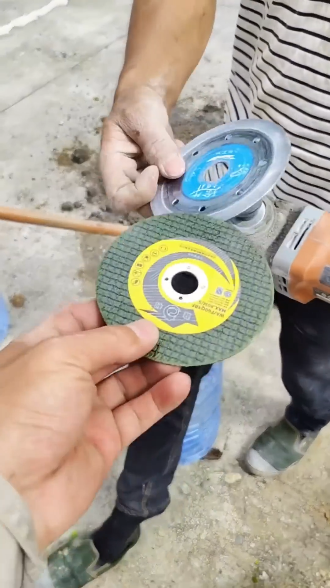
2. Position the New Disc
Place the new cutting disc onto the spindle, ensuring it is seated flat against the inner flange.
-
Crucial Tip: The disc’s label (including the RPM rating and brand) should generally face outward, away from the tool body, making it visible for future reference.
3. Install the Outer Retaining Nut
The outer retaining nut often has two distinct sides: a flat side and a raised hub or recessed side. The correct orientation depends on the type of disc being used:
-
For thin, flat cutting discs (Type 1): The nut should be installed with its flat side facing the disc. This allows for maximum thread engagement on the spindle.
-
For depressed center (hubbed) grinding discs (Type 27): The nut is often flipped, with the raised hub facing the disc, to clamp against the thinner circumference of the disc and provide clearance. Always consult your grinder’s manual for the manufacturer’s recommended orientation.
4. Tighten the Nut
-
Press and hold the spindle lock button again.
-
Use the spanner wrench to tighten the retaining nut clockwise.
-
Do not overtighten. The nut needs to be snug and secure enough to prevent slippage during operation, but excessive force can warp the disc or damage the spindle threads. A firm hand-tightening with the wrench is usually sufficient.
✅ Post-Replacement Inspection and Test
Before returning the tool to service, a final check is necessary to confirm the replacement was successful.
1. Visual Inspection
Verify that the disc is centered and does not exhibit any visible wobble or slant. Ensure all components are fully assembled and the guard is in its correct position.
2. The Run-Up Test
-
Step away from the tool’s working head and ensure no one is nearby.
-
Plug the tool in or insert the battery.
-
Turn the tool on and allow it to run freely at full speed for approximately 30 to 60 seconds.
-
Listen carefully for any unusual vibrations, loud humming, or a noticeable wobble in the spinning disc. If any of these are present, immediately turn off the tool, disconnect the power, and re-examine the assembly. The disc may not be seated correctly, or the flanges may be improperly aligned.